
A door opener with biometric 3D facial authentication for the Raspberry Pi.


With the introduction of the iPhone X in September 2017, Apple established authentication by biometric facial features as a reliable, everyday technology. This project brings that same idea — from the smartphone to the smart home — as a face-recognition front-door opener built around the Intel RealSense ID F455 camera and a Raspberry Pi.
📖 Looking for the developer-facing walkthrough (application flow, code structure, threading model)? See docs/GUIDE.md. This README is the build-and-install guide for makers.
- 🧐 About
- 🏁 Getting Started
- 🔨 Prerequisites
- ⚙️ Functionality
- 🛠️ Hardware Setup
- 💾 Software Installation
- 🔧 Configuration
- 📚 Documentation
- 🎈 Usage
- 🧑🤝🧑 Enrolling Faces
- 🚪 Opening the Door
- 📡 Mosquitto MQTT Broker
- 🔒 Camera Security
- 🚀 Optimization
- ♻️ Intel RealSense ID F455 Status
- 🩺 Troubleshooting
- ✨ Variations & Enhancements
- 📌 Conclusion
- 🎥 Video
- ⛏️ Built Using
- ✍️ Author
- 🎉 Acknowledgements
In early 2021 Intel announced the RealSense ID F455 camera. It applies the same principle of 3D facial authentication and offers makers an attractive product to integrate into self-built solutions. The camera ships with extensive documentation, an open-source SDK for Linux, Windows and Android, and bindings for C, C++, C# and Python.
Unlike Apple's Face ID, it can authenticate more than one person, storing profiles either centrally on a server or in a database on the camera itself. That makes the RealSense ID F455 the perfect candidate for opening a front door by 3D face recognition, with an error rate comparable to an iPhone.

If you are thinking about building a smart door opener with 3D facial authentication, first find an IP interface to your door buzzer. This is the trickiest part of any replica, because requirements differ from door to door and may take some creativity on your end.
For this project we worked with a Siedle bus-based door intercom. Depending on your intercom and IP gateway, you will need to adapt the code that triggers the opener — see Opening the Door. If you do not use MQTT to open the door, set use_mosquitto = false in bin/config.toml and adapt the trigger accordingly.
The hardware for this maker project costs roughly ~500 USD in total, not including an IP gateway to the door buzzer.
Core components
- Intel RealSense ID F455 camera
- Raspberry Pi 4B, ≥ 4 GB RAM, running Raspberry Pi OS
- microSD card ≥ 16 GB
- 5 V power supply, e.g. Meanwell IRM-60-5ST (5 V, 10 A)
- Casing, e.g. the Severina outdoor lamp with sensor by Lindby
- RGB LED matrix 64×32, P2.5, 160×80 mm, e.g. Adafruit 5036
- E18-D80NK IR photoelectric proximity sensor
- 10 kΩ pull-up resistor
- 40-pin GPIO ribbon cable, or 20× female/female jumper wires
- Spacer bolts for the LED matrix: 4× 40 mm, 4× 15 mm, 2× 10 mm (M3)
- 8× M3 nuts to fasten the spacer bolts to the housing plate
- 4× M2.5 12 mm screws to attach the Pi to the housing plate
- ¼-inch screw to fasten the camera to the underside of the housing
- An IP-based interface to your door buzzer (this code assumes MQTT; we used a "Siedle Bus" intercom with an MQTT gateway by Oskar Neumann)
Optional
- Geeek Pi Raspberry Pi 4 Armor Case
- Adafruit RGB Matrix Bonnet
- 40-pin pitch stacking header, to raise the bonnet above the armor case
- PIR sensor HC-SR501, as an alternative to the photoelectric proximity sensor
The smart door opener replaced an outdated entrance light and lives inside its housing. The system is powered from mains voltage only and communicates over the home Wi-Fi — so make sure the mounting location has good Wi-Fi reception.

Smart door opener in the guise of an outdoor light
Because the camera has no presence detector of its own, it is triggered by an infrared reflex light barrier. A visitor wipes a hand past the barrier — or simply leans in a little closer with their face. A faint red glow from the camera's infrared illuminator (mounted upside down at the bottom of the case) appears briefly.
The camera projects invisible 850 nm infrared dots onto the face, records them with two integrated full-HD cameras, and builds a three-dimensional point cloud that it compares against the stored face profiles via AI inference. Authentication takes less than a second; the result — in the positive case, the name of the recognized person — is transferred to the Raspberry Pi over USB. Since we use a single camera, profiles are stored locally on it. (For multiple entrances, the camera also offers a server mode where profiles live on a central server and can be shared by several cameras.)
On success, the recognized name is shown on the LED matrix for a few seconds and the door is opened via an MQTT command over Wi-Fi. When idle, the matrix displays the time, the day of the week and the current date.
See a demonstration on YouTube:
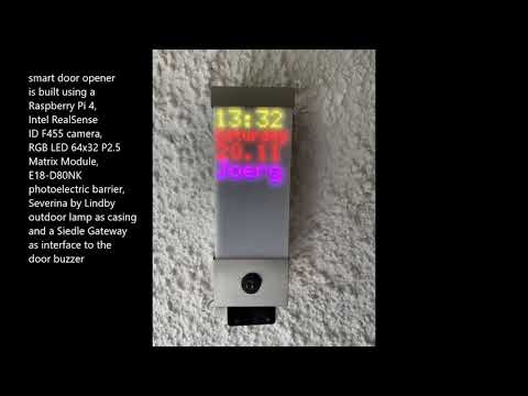
YouTube — how the smart door opener with 3D face recognition works
A Raspberry Pi 4B running Raspberry Pi OS (a.k.a. Raspbian) acts as the host computer. For the housing we chose an outdoor light in a stainless-steel case, which looks inconspicuous by the front door. Alongside the Pi it contains a 50 W, 5 V power supply, a retro-reflective sensor and an Adafruit 5036 LED matrix (64×32 RGB LEDs).
The matrix is mounted to the base plate with four spacer bolts of 55 mm total length each (40 mm + 15 mm). The matrix module is 15 mm thick, leaving 70 mm between the base plate and the frosted acrylic front. To keep the matrix content from blurring behind the satin acrylic, make sure the module sits in direct contact with the acrylic glass.
Before integrating everything into the dismantled lamp housing, wire the components as a prototype and test each part — and the system as a whole.

First test in the prototype build
There are two ways to connect the RGB matrix to the Raspberry Pi.
Option 1 — Adafruit RGB Matrix HAT/Bonnet
The plug-in board offers tidy cabling via the HUB75 connector included with the LED matrix. To keep it clear of the Pi armor case, raise it with a 40-pin pitch stacking header — at the cost of a taller build (approx. 6 cm). Since the Pi is installed opposite the sensor in the lower part of the housing, this is fine for the PIR sensor HC-SR501, but it collides with the 5.5 cm-long E18-D80NK IR light barrier. So when using the E18-D80NK, we recommend either the discrete wiring shown below, or swapping positions — power supply in the lower part, Pi in the upper part.
The Pi is powered via the barrel jack or the screw terminals on the Adafruit Bonnet. The bonnet also uses other GPIO pins for communication, so with the bonnet we use GPIO 19 for the presence sensor. You therefore have to solder a jumper wire for the sensor output onto the bonnet.

Adafruit Matrix Bonnet on a pitch stacking header, soldered to GPIO 19 with a jumper wire over the armor case
Option 2 — Discrete wiring with a 40-pin GPIO ribbon or female-to-female jumper cable

Discrete wiring; the LED matrix on 55 mm spacer bolts wraps around the Pi and power supply

Discrete wiring with jumper cables
Discrete wiring with jumper or ribbon cables is a little more fiddly but just as functional. Here the presence sensor (PIR or photoelectric) connects to GPIO pin 5. The Meanwell power supply has a 4-pin screw terminal on its low-voltage output that powers both the RGB matrix (via the cable included with it) and the Pi (via GPIO pin 2 for 5 V and GPIO pin 39 for GND).
We do not recommend powering the Pi through jumper wires; use a thicker cable with a larger cross-section and firmer terminals instead. We repurposed two spare cable clamps from the LED matrix power supply, pulled them out with a small screwdriver, and covered them with heat-shrink tubing to avoid any short circuit on GPIO pin 2.

Repurposing two 5 V power leads from the LED matrix module to supply the Pi
Detailed instructions for the discrete wiring of the LED matrix are here: https://github.com/hzeller/rpi-rgb-led-matrix/blob/master/wiring.md

Camera mounted face down on the bottom of the case
The camera is mounted upside down on the underside of the housing. Its included USB-C cable is fed into the housing through a hole drilled behind the camera and plugged into one of the four USB-A ports on the Raspberry Pi.
The frontal housing hole originally intended for the PIR lens is filled with the reflex infrared light barrier, secured inside and out with the two enclosed plastic nuts. With the Adafruit Matrix Bonnet, the sensor is powered with 5 V from the bonnet: route the brown wire to the terminal labelled "5V Out".
With discrete wiring there are several ways to get 5 V from the GPIO header — e.g. +5 V on pin 4 and GND (blue wire) on pin 34. The sensor output (black wire) connects to pin 29, i.e. logical GPIO 5.
If you don't have a wall or similar infrared-reflecting object opposite the door, you can use a PIR sensor (e.g. the HC-SR501) instead of the light barrier. In our case, though, the PIR produced many false positives and frequently triggered the camera: the LED matrix flickers invisibly to the human eye, and this irritated the PIR sensor via a reflecting wall opposite.
The housing of Lindby's Severina sensor-controlled outdoor wall light fits the 160 × 80 mm RGB LED matrix and offers just enough room for all components. Mounting it requires drilling a few holes in the rear panel.

Rear panel with additional drill holes
The camera is fastened to the lower stainless-steel plate from inside the housing with a ¼-inch screw. To stop the valuable camera from simply being twisted off, it is secured with two 10 mm spacer bolts.

Spacer bolts as an anti-theft device — and a still-missing cable grommet 😮
smartdoorF455 is a C++17 application. All behavior is controlled through the configuration file bin/config.toml — there is nothing to #define or recompile for normal setup changes.
The build uses CMake presets. On the first configure, CMake automatically fetches and builds the project-specific dependencies (RealSense ID SDK, tgbot-cpp, toml++, WiringPi, rpi-rgb-led-matrix, PeriodicExecutor), so you only need to install the system libraries yourself. On a Raspberry Pi the first build takes a while.
# 1. System packages (Raspberry Pi OS / Debian)
sudo apt-get update && sudo apt-get upgrade -y
sudo apt-get install -y git cmake build-essential
sudo apt-get install -y libopencv-dev libssl-dev libmosquitto-dev \
                        libboost-thread-dev libboost-chrono-dev

# 2. Get the source
git clone https://github.com/joergwall/smartdoorF455.git
cd smartdoorF455

# 3. Configure and build (CMake fetches the remaining dependencies)
cmake --preset default
cmake --build build -j4

# 4. Optional: install the binary to /usr/local/bin
sudo cmake --install build
After a successful build:
- the executable is at
bin/smartdoorF455, - the LED-matrix fonts (
6x12.bdf,4x6.bdf) are copied intofonts/, - runtime logs and the PID file go to
log/at the project root.
If you prefer not to use the preset, the equivalent is:
cmake -S . -B build -DCMAKE_BUILD_TYPE=Debug && cmake --build build -j4
Copy the annotated example to bin/config.toml and edit it to match your hardware and network:
cp bin/config.toml.example bin/config.toml
$EDITOR bin/config.toml
Every key has a safe default; the example file documents each one inline. The main sections are:
[raspi]—gpio_sensor_pin(use19with the Adafruit Bonnet, otherwise5),gpio_sensor_pull(0=off,1=down,2=up), andwait_time_until_reauthentication(cooldown in seconds).[mosquitto]—use_mosquitto,host,port,keepalive,client_id,topic_door(where theopencommand is published) andtopic_control.[camera]—camera_rotation,security_level,algo_flow,dump_mode,matcher_confidence_level,frontal_face_policy,max_spoofs,gpio_auth_toggling. These map directly onto the RealSense ID device config.[matrix_options]—hardware_mapping("adafruit-hat"for the bonnet,""for discrete wiring),brightness,pixel_mapper_config, the various*_colortriples and an optionalfont_dir.[telegram]—use_telegram,bot_token,chat_id,send_snapshot.
For example, this is roughly the configuration we run:
# This is a TOML config file for smartdoorF455
title = "TOML configuration file for smartdoorF455"

[raspi]
gpio_sensor_pin = 5  # 19 if the Adafruit Bonnet is used, otherwise 5
gpio_sensor_pull = 2 # 0=PUD_OFF, 1=PUD_DOWN, 2=PUD_UP (see WiringPi)
wait_time_until_reauthentication = 5 # seconds until the next attempt is allowed

[mosquitto] # MQTT used for door communication
use_mosquitto = true
host = "localhost"
port = 1884
keepalive = 600
client_id = "smartdoorF455"     # unique client_id
topic_door = "siedle/exec"      # topic that opens the door
topic_control = "smartdoorF455" # topic for interactions such as user enrollment

[camera] # see https://github.com/IntelRealSense/RealSenseID/blob/master/include/RealSenseID/DeviceConfig.h
camera_rotation = "180"          # 0 (default), 90, 180, 270
security_level = "Low"           # High, Medium, Low (default)
                                 # Medium/High caused too many false spoof
                                 # reports in our tests (v1.3.1 / May 2025)
algo_flow = "All"                # All, FaceDetectionOnly (default), SpoofOnly, RecognitionOnly
dump_mode = "CroppedFace"        # None (default), CroppedFace, FullFrame
matcher_confidence_level = "High"# High, Medium, Low (default)
frontal_face_policy = "Moderate" # Strict, Moderate, None (default)
max_spoofs = 0                   # max consecutive spoof attempts before rejection
gpio_auth_toggling = 0           # 1 = toggle GPIO after successful auth, 0 = off (default)

[matrix_options] # LED matrix display
# font_dir = ""                  # optional absolute path to the .bdf fonts;
                                 # when empty, fonts are auto-located
hardware_mapping = ""            # "adafruit-hat" for the bonnet, "" for discrete wiring
brightness = 80                  # 0..100 percent
pixel_mapper_config = "Rotate:270" # "Rotate:0" | "Rotate:90" | "Rotate:180" | "Rotate:270"
clock_color = [255, 255, 0]      # RGB, values 0..255
date_color = [255, 28, 0]
day_color = [255, 28, 0]
username_color = [255, 0, 255]
bg_color = [0, 0, 0]             # background (default black)
outline_color = [0, 0, 0]        # outline (default none)

[telegram] # optional: forward event messages to a Telegram bot
use_telegram = false
# bot_token = "[enter your telegram bot_token here]"
# obtain chat_id from https://api.telegram.org/bot<YourBotToken>/getUpdates
# chat_id = [enter chat_id number here]
send_snapshot = true # send a photo of each authentication attempt.
                     # Mind data-privacy/GDPR implications, especially if the
                     # image can include parts of non-private property.
bin/config.tomlmay contain secrets (your Telegram bot token) and is git-ignored. Keep onlybin/config.toml.exampleunder version control.
Two complementary documents describe the software:
- docs/GUIDE.md — a human-readable developer & user guide (application flow, code structure, threading model, troubleshooting table).
- Doxygen API reference — generated from the Doxygen-style comments in the source.
The source is organized into a small, focused C++17 codebase under src/: the entry point src/main.cpp, the runtime orchestration in src/application.cpp / src/application.hpp, configuration handling in src/config.cpp / src/config.hpp, and display rendering in src/matrix_display.cpp / src/matrix_display.hpp.
To generate the HTML API reference:
# via the CMake target (recommended)
cmake --build build --target doc

# ...or directly, from the project root
doxygen src/doxygen.conf
Then open docs/html/index.html.
The application is managed through the launcher script in bin/:
cd bin
./run_smartdoorF455.sh start        # start in the background
Other useful commands:
./run_smartdoorF455.sh status       # is it running? (reports the current PID)
./run_smartdoorF455.sh stop         # stop the running process
./run_smartdoorF455.sh restart      # stop, then start
./run_smartdoorF455.sh foreground   # run attached to the terminal
./run_smartdoorF455.sh start --config /path/to/custom-config.toml
./run_smartdoorF455.sh start --logdir /path/to/logs --no-taskset
The launcher writes its log output and PID file to the log/ directory at the project root. Even before any face has been enrolled, the LED matrix should show the time, weekday and date. If it doesn't, see Troubleshooting.
To teach the camera the faces of authorized users, use the command-line tool from Intel's RealSense ID SDK. If the device /dev/ttyACM0 is missing, try /dev/ttyACM1 instead.
In the tool's menu, use s to set the rotation to match how the camera is mounted (0 upright, 180 upside down — as it is when screwed to the underside of the housing). Then use e to enroll a user with the profile stored locally on the camera. Hold the face about 30–50 cm from the camera.
# install the Intel RealSense ID SDK (for the enrollment CLI)
git clone https://github.com/IntelRealSense/RealSenseID.git
cd RealSenseID
mkdir build && cd build
cmake .. -DRSID_PREVIEW=1
make -j4

# run the enrollment CLI
cd ~/RealSenseID/build/bin
sudo ./rsid-cli /dev/ttyACM0
Connected to device
Authentication settings:
* Rotation: 0 Degrees
* Security: High
* Algo flow Mode: All
* Face policy : Single
* Dump Mode: CroppedFace
* Matcher Confidence Level : High
Please select an option:
'e' to enroll.
'a' to authenticate.
'd' to delete all users.
'c' to capture images from device.
's' to set authentication settings.
'g' to query authentication settings.
'u' to query ids of users.
'n' to query number of users.
'b' to save device's database before standby.
'v' to view additional information.
'x' to ping the device.
'q' to quit.
server mode options:
'E' to enroll with faceprints.
'A' to authenticate with faceprints.
'U' to list enrolled users
'D' to delete all users.
> e
User id to enroll: Julia
Connected to device
*** Hint Success
*** Hint Success
Repeat this for every authorized person.
Note on names: the LED matrix can only show a limited number of characters. With the default 6×12 font, roughly 5 characters fit the rotated panel. Use an abbreviation, or edit the username draw call in
src/matrix_display.cppto use the narrowerfont4x6_(up to ~8 characters) and rebuild.
To unlock the front door with this solution, your door intercom must expose an IP interface. If you plan a replica, analyze your bell system in detail first and look for ways to add such an interface.
Our Siedle bus-based intercom is driven through a gateway by Oskar Neumann that translates MQTT commands into the Siedle bus over Wi-Fi (this gateway is no longer on the market). Siedle offers the Smart Gateway SG-150 as an IP interface, but at 600+ USD it is a hefty investment for a DIY project. Other Siedle IP interfaces we have not tested include third-party gateways such as Hamares and the smart opener from SMS Guard, which also provides an MQTT interface.
If you already run an IP-based intercom, you're in luck. The door is opened by the Application::publishDoorOpen() function in src/application.cpp, which publishes the message open to the configured topic_door. To drive a different interface, adapt that function. For example, if your opener can be triggered by an HTTP request, replace the MQTT publish with a system call:
// Example: open the door via an HTTP request instead of MQTT.
// Assumes the opener responds to:
//   http://192.168.178.27:8083/fhem?cmd=set%20Siedle%20open
// Make sure curl is installed: sudo apt install curl
// and set use_mosquitto = false in bin/config.toml.

system("curl 'http://192.168.178.27:8083/fhem?cmd=set%20Siedle%20open'");If you use MQTT to communicate with the door opener, create this configuration for the Mosquitto broker on the Pi:
sudo apt-get install -y mosquitto mosquitto-clients
sudo nano /etc/mosquitto/conf.d/mymosquitto.conf
Add the following lines:
listener 1883
listener 1884
allow_anonymous true
Then restart the broker:
sudo systemctl restart mosquittoFor debugging, a Mosquitto client lets you eavesdrop on the messages exchanged by the broker:
mosquitto_sub -d -t "#"In c't 6/2018, p. 164 (German) Jan Mahn explains MQTT in detail, including how to protect it with encryption — which we omitted here for simplicity. As a result, this solution is only as secure as your home Wi-Fi. That article is recommended reading for any maker considering MQTT.
The RealSense ID SDK offers a secure communication mode that pairs the camera with the host and encrypts their communication. This prevents an uninvited guest from gaining access by quickly plugging in another RealSense ID camera over USB-C with their own face profiles. We did not enable this mode here for simplicity. Instructions are available upstream:
https://github.com/IntelRealSense/RealSenseID#secure-communication
To reserve one of the four CPU cores exclusively for our application (and remove it from the process scheduler), edit:
sudo nano /boot/cmdline.txtAppend isolcpus=3 to the end of the single line, so it looks similar to:
console=serial0,115200 console=tty1 root=PARTUUID=e0d8ecc0-02 rootfstype=ext4 fsck.repair=yes rootwait quiet splash plymouth.ignore-serial-consoles isolcpus=3
This takes effect after a reboot and helps prevent LED-matrix flicker. The launcher script pins the process to the isolated CPU using taskset when starting (disable with --no-taskset).
Intel discontinued the RealSense ID F455 on February 28, 2022. It later reversed that end-of-life decision (2024), spun the entire RealSense camera line off into a separate RealSense corporation, and happily breathed new life into the camera. The most up-to-date information on the facial-authentication products is here.
When replicating this build (power supply, LED matrix, Pi and, optionally, matrix bonnet), small issues can crop up. Here are the ones we know about.
Power supply. The Pi is sensitive when its supply voltage drops below the critical 4.63 V — the red LED starts to blink or goes dark entirely. The Meanwell supply delivers a stable voltage, but as noted under Wiring, use a sufficient cable cross-section and firm terminals. If in doubt, measure the voltage at GPIO pins 2/4 and 6 with a multimeter and reinforce with an additional cable if needed.
Distorted image on the LED matrix. When the LED matrix bonnet is raised via a 40-pin pitch stacking header, a flaky header can cause problems. In particular, the one bundled with the armor case gave us trouble. Electronics suppliers offer gold-plated pitch stacking headers cheaply; those have served us well.
First, check the most recent log file for informative error messages:
cd log
ls -la
more ./20211216_092446_smartdoorF455.log
Couldn't load font files / failed to load matrix fonts. Ensure the fonts/ directory exists and contains 6x12.bdf and 4x6.bdf (rebuilding regenerates it), or set font_dir in the [matrix_options] section of bin/config.toml to the absolute path of the fonts.
on_result: Error. You wave your hand in front of the sensor, but there's no faint red glow from the camera's infrared illuminator — the camera won't start authentication. After a reboot, the camera sometimes fails to initialize on the first launch. Stop and restart the application:
./run_smartdoorF455.sh restartinitInitialise: Can't lock /var/run/pigpio.pid — cannot initialize GPIO. Another process is holding the GPIO. Restarting the application (as above) usually clears this.
LED matrix stays dark. No error in the log and the matrix is wired correctly, yet the display remains dark? The hardware_mapping setting is likely wrong for your wiring. Set it in the [matrix_options] section of bin/config.toml: use "adafruit-hat" with the Adafruit Bonnet, or "" (empty) for discrete wiring, then restart.
In our experience, once the software is up and running it stays stable for days and weeks. Even grandma now leaves her key at home and relies on face control to get in.
No RGB matrix module. If you want to skip the LED matrix, a single multicolor RGB LED can indicate authentication status instead. That removes the need for the powerful 5 V / 10 A supply — the Pi's usual USB-C power supply is enough — and lets you slim the project down into a smaller housing.
Ubuntu instead of Raspberry Pi OS. Raspberry Pi OS is robust and makes optimal use of the hardware, but Intel's RealSense ID SDK has only limited support on it. As an alternative we successfully tested Ubuntu Linux 20.04. Ubuntu becomes interesting for extended RealSense ID features, such as capturing camera snapshots to send via a Telegram bot. If you want to explore the SDK further, we recommend flashing a separate SD card with Ubuntu for that task.
Pixel art to cheer up the neighbors. To play fun animations on the LED matrix, use the example programs under rpi-rgb-led-matrix/utils. For instance, you can display a GIF animation like this:
# install rpi-rgb-led-matrix by Henner Zeller
git clone https://github.com/hzeller/rpi-rgb-led-matrix.git
cd rpi-rgb-led-matrix/
make -C examples-api-use

# build the utils and fetch a spinning Super Mario GIF
cd utils/
make
wget https://media1.giphy.com/media/QxZEtFE02ofY00gJ71/giphy.gif

# discrete wiring:
sudo ./led-image-viewer --led-rows=32 --led-cols=64 --led-brightness=90 \
     --led-pixel-mapper "Rotate:270" --led-rgb-sequence=RBG \
     --led-no-hardware-pulse ./giphy.gif

# ...or with the Adafruit RGB Matrix Bonnet:
sudo ./led-image-viewer --led-rows=32 --led-cols=64 --led-brightness=90 \
     --led-pixel-mapper "Rotate:270" --led-rgb-sequence=RBG \
     --led-gpio-mapping=adafruit-hat --led-no-hardware-pulse ./giphy.gif
Pixel art: spinning Mario
For a deeper dive into the LED matrix options, see Pixelart mit Pi, Make magazine 5/2021 by Daniel Bachfeld (German).
User authentication by three-dimensional biometric face recognition is a young field that opens up exciting scenarios for the maker community. Our door opener — or, more precisely, door release, since you still open the front door yourself — has done its job reliably for weeks. We are enthusiastic about this 3D camera, and glad that, after a brief end-of-life scare, it lives on under the new RealSense corporation.
A quick demonstration of the functionality:
- RealSenseID — SDK for the Intel RealSense ID F455
- rpi-rgb-led-matrix — Henner Zeller's LED-matrix API
- WiringPi — GPIO access on the Raspberry Pi
- toml++ — TOML configuration parsing
- tgbot-cpp — Telegram Bot API
- PeriodicExecutor — periodic task execution
- Joerg Wallmersperger — maker and user of smartdoorF455
- Olaf — inspiration and tech support
- Oskar Neumann — the MQTT gateway to our door intercom