
Pomodoro tracker implementation for Arduino Uno R3 (or compatible) using a Multifunction Shield and a DS1302 RTC module. It helps manage work in focused sprints, track productivity with daily historical statistics stored in EEPROM and customize timer behavior with various settings.
The runUp device is easy to assemble and requires no soldering. It uses widely available, low-cost components, making it accessible for hobbyists and beginners. The Multifunction Shield plugs directly onto the Arduino Uno and the DS1302 RTC module connects via simple jumper wires.
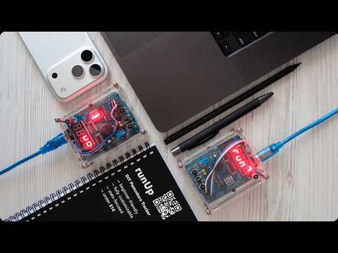
The device can be placed into a simple DIY enclosure. Using two transparent acrylic Arduino Uno cases, hex standoffs, bamboo sushi stick and heat-shrink tubing, you can easily build a good-looking case.
The runUp device follows the classic Pomodoro technique. Work sessions last 25 minutes, during which you should focus solely on your task without distractions. Short 5-minute breaks occur between each session and after every four completed sessions, a longer 15-minute break is taken. This cycle repeats continuously to help maintain focus and productivity.
| Session Type | Duration | Notes |
|---|---|---|
| Work | 25 min | Focused work, no distractions |
| Short Break | 5 min | Quick rest, stretch |
| Long Break | 15 min | After every 4 work sessions, extended rest |
🎬 Watch the Video Demonstration on YouTube
The Statistics menu contains statistical data that allows you to track your progress.
- Saves the number of completed sprints per day in EEPROM
- Provides flexible periods for calculated statistics, including daily, monthly, and yearly data
- Shows statistics with minimum, average and maximum values
There are one-click modes: temporary modes activated while the device is powered on with a simple button hold. These modes are not saved, so there is no need to manually toggle settings in the Configuration menu. Once the device is turned off, the temporary modes are reset.
- Silent mode: turns off all sounds
- No-Music mode: turns off melody playback but keeps simple beeps
- Hero mode: repeats 25-minute work sessions without breaks
There are also customizable settings that can be saved in EEPROM through the Configuration menu:
- Display: 4 brightness levels
- Sound: silent mode, simple beeps or 14 built-in melodies
- Reminders: beeps during pauses or breaks
- LED: progress indication via flickering light
- Statistics: flexible calculation logic with selectable units (hours or sprints)
- Only weekdays
- Weekdays and weekends
- All non-zero days
- Hero mode: repeats 25-minute work sessions without breaks
- Sleep mode: reduces power consumption
The RTC (real-time clock) module keeps track of the current date and time even when the device is powered off. The date and time can be set through the Clock menu, making it easy to monitor daily progress and align work sessions with real-world schedules.
- Arduino Uno R3 (or compatible)
- Multifunction Shield (MFS)
- DS1302 RTC module (with CR2032 battery)
- DuPont jumper wires (5x female-to-female, 20 cm each)
- Power cable for Arduino

The RTC module is hidden between the two boards to save space and keep the build compact:

⚠️ Warning: When mounting the Multifunction Shield on the Arduino Uno with a USB Type-B socket, ensure the underside of the shield does not touch the metal parts of the socket. Contact may cause a short circuit when powering the device. Use a thin piece of insulating material (like a plastic card) between the boards to prevent accidental contact.
- DS1302 connects to MFS pins:
RST→~5DAT→~6CLK→~9VCC→+5VGND→GND
- MFS (with jumper near the buttons) plugs directly onto Arduino
- USB power cable (5 V) or external power connects to Arduino

If you plan to build an enclosure or want to keep the DS1302 RTC module hidden under the MFS, you may need to trim the module's corners (depending on the board's component layout) and bend its contacts to 90° so it can fit between the boards, as shown with red marks in the illustration below. Do this carefully to avoid damaging the module's tracks.

⚠️ Warning: Be sure to insulate the DS1302 RTC module with tape to prevent accidental damage or short circuits. You may also need to trim the pins or leads of the module's components if they are too long and prevent it from fitting between the boards.
On the MFS, place a jumper wire from the bottom-right group of pins, routing it between the buzzer and the blue trimmer resistor and then up through the top side of the shield, as shown with green marks above. From there, lead the wire through the top part of the Arduino (between the USB socket and the 9V power input) and connect it to the DS1302, which is located between the boards.
Note that the wire routing and RTC module position depend on the board's component layout and the jumper wire length, so they may differ from the illustration shown here in your case.
The enclosure is based on two similar Arduino acrylic cases, whose walls are held together with hex standoffs and heat shrink tubing:

You will need the following tools to build the enclosure:
- Wire cutters, pliers, awl, utility knife (for case walls, holes and button rods)
- Flat and round files or sandpaper (for smoothing and adjusting case walls and rod edges)
- Lighter or matches (for shrinking heat-shrink tubing)
- Black permanent marker (for coloring button rods)
The enclosure can be assembled from the following components:
- Two transparent acrylic Arduino Uno cases
- Hex standoffs (M3 threaded, with screws and nuts) for fixing the enclosure
- Bamboo sushi stick pieces as button rods
- Heat-shrink tubing to hold button rods and case walls in place
It's best to have sets of different M3 hex standoffs and heat-shrink tubing to test-fit the optimal sizes. In my case, the following dimensions worked best:
Optimal body length: 2 x 32 mm (bottom part) and 2 x 30 mm (top part). These measurements refer to the standoff body only and do not include the 6 mm threaded sections on each end. They can be combined from 20 mm, 12 mm and 10 mm pieces.
Optimal inner diameter: 6 mm for the button rods, 3 mm for the case walls.
For the front (with buttons) and back (opposite) sides of the enclosure, use two big bottom parts of Arduino Uno acrylic cases, as shown below.

If you plan to use M3 threaded hex standoffs, first enlarge the four corner mounting holes in the front and back parts of the enclosure (see red marks). Then mount the Arduino with screws on the back side of the enclosure and plug the MFS directly onto it.
Assemble the front and back sides of the enclosure, then mark the positions of the future button holes — 3 for MFS bottom buttons and 1 for reset button — on the front panel, as shown with purple marks in the illustration below.

Make the holes with an awl and carefully enlarge them with a round file until they match the diameter of your button rods (sushi sticks or something similar). Try to make it as precise as possible, because if the holes are too large or misaligned with the buttons, pressing them and using the runUp device will be difficult.
Cut the sushi sticks into 4 pieces: 3 for the MFS bottom buttons (about 14 mm high) and 1 for the reset button (about 11 mm high). The reset button rod is shorter due to the height difference between the top and bottom parts of the enclosure. The jump wire connectors at the bottom increase the height, but if you are comfortable with soldering, you can make the enclosure symmetrical.
Exact dimensions may vary depending on your specific board, so remember: measure twice, cut once. Each button rod should extend roughly 1-2 mm above the front surface of the enclosure, because if the rods are too short or too tall, pressing them will be difficult.
Once you have finished sizing the rods, use a utility knife to make small recesses on the bottom side of each rod — this will make them more stable when mounted on the MFS buttons. Then slide a heat-shrink tube onto each rod (inner diameter 6 mm), leaving about 3 mm length exposed at the top and use a lighter to shrink the tube. This will hold the rods in place so they won't fall out if you turn your device upside down.

Use a black permanent marker to color the button rods so the heat-shrink tubing blends in.
Assemble case parts with the standoffs and test-fit the case walls to check the alignment.
Use a utility knife and a flat file to adjust the walls at the marked positions (shown below) until they fit properly with the standoffs. Secure each pair of walls in a stacked position with heat-shrink tubing (3 mm fits well, even without heating).

After routing the jumper wire and assembling the enclosure, the device should look like this:

The runUp device uses my fork of the Multifunction Shield library by Kashif Baig and Cohesive Computing. It also requires the Rtc library by Michael Miller (Makuna), along with the built-in Arduino libraries for EEPROM and Sleep mode support.
- Multifunction Shield library
- RTC library
- Built-in: EEPROM, avr/sleep
After assembling the device and reading the note below, upload the program sketch via USB cable using the Arduino IDE or any other environment that supports uploading. If everything works as expected, the display will either show the first menu item or the date and time settings, depending on your setup and initial conditions (such as the RTC module settings and EEPROM contents).
ℹ️ Note: The device uses EEPROM. If your Arduino already has data stored there, you'll need to clear it for proper operation. This can be done directly with the device, as you will see later.
There are 4 buttons to operate the device. The Reset ◆ button is located at the top right corner and works the same way as on standard Arduino boards.
At the bottom of the MFS, there are three buttons used to operate the device menu and its functions:
- Back
◀: exit or cancel - Switch
▲▼: switch the current menu item or adjust a value - OK
▶: enter a menu or confirm a selection

If this is the first run with a fresh battery, you need to set the current date and time for the device to work properly.
ℹ️ Note: In rare cases, the RTC may fail to set the date and time on the first attempt. This can happen if the RTC has not yet synchronized or if write protection is enabled. If this occurs, an error message will be shown. To fix the issue and set the correct date and time, see the Error handling section.
If everything works correctly, after powering on you will see the initial values, with the first digit blinking:


Follow the Editing date and time section to configure the current date and time.
After completing the setup, the device will return to the main menu, which contains four top-level items: run, data, conf and cloc. Use the Switch ▲▼ button to cycle through the menu items, the OK ▶ button to enter a selected menu and the Back ◀ button to exit.


This is one of the main menus used to start and manage sprints. Press the OK ▶ button to enter this menu. After a short animation showing your daily progress, you will see the timer value. If there is no active interval, the default 25-minute sprint interval is shown; otherwise, the remaining time of the current sprint is displayed.
In the run menu, press the OK ▶ button to start or continue the sprint. The countdown timer will then appear on the device's screen. The four on-board LEDs show progress in blocks of four intervals: completed ones stay lit and the current one blinks. LEDs are active only if the Flicker setting is enabled (see LED Indication).
ℹ️ Example: After completing the first sprint, the first LED stays on; when the second sprint starts, the second LED blinks while the first remains lit; after completing the second sprint, both the first and second LEDs stay on and the third LED starts blinking during the third sprint. This pattern continues and after completing four intervals, the LED cycle loops again, showing progress for the next set of four sprints (we are limited to four LEDs on the device).
The best strategy is to concentrate on your work and complete the sprint without any interruptions or distractions. But life is life, so if your cat decides to stress-test your brand-new sofa or if there is an asteroid fall alert, you will probably need to pause for a minute or two. In these cases, press the OK ▶ button and your current sprint will be paused. Press it again to resume when ready.
During a pause, the last digit on the display will blink. Also, if the Cue setting is enabled (see Reminders), the buzzer will emit a short beep every minute to remind you that the sprint is paused.
If you need to exit to the main menu during a pause to view statistics or change settings, your current sprint will be held until you turn off the device or resume the sprint.
If you need to cancel the current sprint, pause it first, then press and hold the Back ◀ button for 2 seconds. After that, the device will reset the current sprint and show the default 25-minute sprint interval, keeping you in the run menu.

Press the OK ▶ button to start a new sprint or the Back ◀ button to exit to the main menu.
There are three temporary one-click modes to enhance your sprint experience. They can be enabled or disabled only during a sprint by pressing and holding one of the buttons for 2 seconds. These modes are temporary; they remain active only until you turn off the device or disable them manually.
ℹ️ Example: If there is an emergency online meeting with your very serious colleagues and A-ha – Take On Me does not feel like the most appropriate background music, all sounds can be temporarily disabled using the Back
◀button, without opening the settings or interrupting your workflow. Once the meeting ends, you can re-enable sound using the same button.
Once you press and hold the appropriate button, an information alert showing the current mode and its status (on or off) will appear on the display.


Press and hold the Back ◀ button to mute the buzzer and disable all sounds.

Press and hold the Switch ▲▼ button to turn off melody (tunes) playback while keeping simple beeps.


Press and hold the OK ▶ button to repeat 25-minute work sessions without breaks, like a hero.
After the sprint is completed, a success message is displayed on the screen with a short animation indicating your current daily progress. Once the animation finishes, the sprint counter is saved to EEPROM at the cell corresponding to the current day of the year.
If the device is powered off or enters Sleep mode, your progress will not be lost, as it is stored in non-volatile EEPROM memory. When you turn the device back on, the latest sprint counter for the current day is restored. If no counter is saved for the current day, it starts from 0. If you skip some days, their values will also be filled with zeros for data consistency.
If an interval is started near midnight and finishes the next day, the sprint counter is saved to the next day's cell. This is because progress is recorded only when the interval is completed, regardless of when it was started.


This is one of the main menus used to view and manage statistical data. Press the OK ▶ button to enter it. The menu contains several elements showing different metrics:
- Now: progress for today
- Daily: daily progress for any day of the year
- Total, Minimum, Average, Maximum: calculated statistics for a selected period
- Clear: erase all statistics
The device currently uses 366 EEPROM cells to store sprint data, one cell for each day of the year. If you use the device for more than a year, older data will be overwritten.
Statistical data calculation depends on the Counted Days setting. This setting defines which days of the week are included in the calculation (weekdays, extended weekdays, all days or any day with recorded activity).
All statistics are displayed using the selected counting unit (number of sprint runs or hours). This can be changed using the Counting Units setting.


The now submenu displays your current statistics for today, automatically cycling between sprint count and total hours every 1.5 seconds. To exit this submenu (as well as any other submenu, since this behavior is consistent), press the Back ◀ button.

The daily submenu displays your statistics for any day of the year except today. After entering this menu, use the Switch ▲▼ button to select a specific date, then press the OK ▶ button to view it and the Back ◀ button to exit.
For faster date selection, press and hold the Switch ▲▼ button. Dates scroll backward, starting from yesterday and moving further into the past.


There are four submenus with the same logic, so they are grouped into a single section here:
- Total statistics by period (totl submenu)
- Minimum statistics by period (min submenu)
- Average statistics by period (mid submenu)
- Maximum statistics by period (max submenu)
In any of these submenus, use the Switch ▲▼ button to select a period, then press the OK ▶ button to view it and the Back ◀ button to exit. These submenus display different types of statistics – total, minimum, average and maximum values – for the following periods:
- Rolling 365 days
- Rolling 100 days
- Rolling 60 days
- Rolling 30 days
- Rolling 7 days
- A specific month
ℹ️ Note: If you have been using the device for a long time, its memory may be full and older data will be overwritten as intended. For example, if it is currently June and you try to view August data, the device cannot show future data, so it interprets it as past data and displays the same period from last year (if the device was in use at that time).


The clr submenu allows you to clear all statistics data. After entering this submenu, a clr all data warning is displayed. The LEDs will blink to indicate that this is a destructive action. If you are sure you want to proceed, press and hold the OK ▶ button for 2 seconds to clear all data.
⚠️ Warning: This action cannot be undone. Make sure you have a backup of your statistics if you might need them later. You can create a backup by connecting the device via the serial port using the Arduino IDE.

This is one of the main menus used to configure the device. Press the OK ▶ button to enter it. The menu contains several customizable settings:
- Display
- Buzzer
- Melodies
- Reminders
- LED Indication
- Counted Days
- Counting Units
- Hero mode
- Sleep mode
- Software Build
- Author Info
Use the Switch ▲▼ button to select a setting and press the OK ▶ button to view its value. Change the value using the Switch ▲▼ button.
Press OK ▶ to save the change or Back ◀ to exit without saving.

Adjust the display brightness (4 levels) or temporarily turn the display off. To turn the display back on, press any button. Note that power consumption may increase by 2–3x when using the maximum brightness level compared to the minimum level.
An attentive user may notice that the device uses a segment LED display, not a liquid crystal display (LCD). However, to keep the settings simple and familiar, the well-known LCD abbreviation is used here. In this case, you may think of it as standing for "LED Characters Display".
Enable or disable the on-board buzzer. If this setting is disabled, the device will be silent and the next two settings (tune and cue) will be hidden.
If you only need Silent mode occasionally, it can be temporarily enabled using One-Click modes.
Select one of 14 built-in tunes, random playback or simple beeps for work session completion. The following melodies are available and can be selected by number:
- Koji Kondo - Super Mario Bros. (Flagpole Fanfare)
- Koji Kondo - Super Mario Bros. (Overworld theme)
- Henry Mancini - Baby Elephant Walk (intro)
- Henry Mancini - Baby Elephant Walk (outro)
- Hirokazu Tanaka - Type A (Tetris)
- Elderbrook & Vintage Culture - Run
- K.Flay - Not In California
- Lana Del Ray - Summertime Sadness
- Coldplay - Clocks
- Metallica - Master Of Puppets
- Little Barrie - Better Call Saul theme
- Gorillaz - Clint Eastwood
- Fontaines D.C. - Starbuster
- A-Ha - Take On Me
Selecting rnd will play a random melody. Selecting off will disable melodies and use simple beeps instead.
If you only need No-Music mode occasionally, it can be temporarily enabled using One-Click modes.
Enable or disable audio reminders during pauses and breaks. When enabled, the device will beep every minute while a sprint is paused or during breaks between sprints, reminding you to resume the sprint or take a rest.

Enable or disable progress indication using a flickering on-board LEDs. The indication logic is based on four intervals, as described in the Start the sprint section above.
Select which days are included in statistics: weekdays, extended weekdays, all days or any day with recorded activity.
- 1-5d: Monday to Friday
- 1-6d: Monday to Saturday
- 1-7d: Monday to Sunday
- not0: Any day with non-zero sprints
Select the units used for statistics: number of sprint runs or hours. This setting affects statistics only. After completing a sprint, your progress will still be shown in both runs and hours.
Enable or disable continuous 25-minute work sessions without breaks. When enabled, the device works as a simple work time instead of using the Pomodoro technique logic.
If you only need Hero mode occasionally, it can be temporarily enabled using One-Click modes.
Enable Sleep mode (hibernation) with reduced power consumption. In this mode, the device consumes 10-20 mA, while in normal operation it consumes about 45 mA at minimum brightness and 100+ mA at maximum brightness.
There are two ways to wake up the device: by short-circuiting the interrupt (ISR) pin 2 to any GND pin or by pressing the Reset ◆ button. Pressing Reset is easier, but if you have an unfinished sprint, it will be lost after the reset.
Display the current software version installed on the device. This information can be useful when checking compatibility with the documentation, reporting issues or verifying that the firmware was updated successfully.
Display basic information about the project author with a GitHub profile link.
This is one of the main menus used to configure the date and time. Press the OK ▶ button to enter it. The device will display the current time. Use the Switch ▲▼ button to toggle between the current time, date and year.
In this menu, on any screen (time, date, or year), press the OK ▶ button again to start editing. For example, assume you press it on the time screen.
This mode is entered either from the cloc menu or automatically on the first run. The first digit will begin blinking.
Use the Switch ▲▼ button to change the current digit, then press OK ▶ to move to the next one. Set the hours first, then the minutes. After setting the time, the device will switch to date input. The current date and month values will be displayed.
Use the Switch ▲▼ and OK ▶ buttons to change the digits, just like before. After you set the date and month, do the same to set the year (just the last 2 digits – changing the first two might make your device question reality):
When you're done, press and hold the OK ▶ button for 2 seconds to save your changes and exit the date and time setup.
During device operation, errors may occur. For convenience, each error is assigned a specific code for easier identification and troubleshooting.

The real-time clock (RTC) has stopped or is not running. This usually happens when the RTC module has not been initialized or has lost power.
Press and hold the OK ▶ button for 2 seconds to enter the Editing date and time mode. Then set the correct date and time following the instructions above.
If the issue persists, power off the device and check the RTC battery and wiring for loose contacts or poor connections.
The device detected that the stored date or time is incorrect or corrupted. Reconfigure the date and time to restore normal operation.
Press and hold the OK ▶ button for 2 seconds to enter the Editing date and time mode. Then set the correct date and time following the instructions above.
The system detected an existing invalid record during startup or while saving a sprint. This usually happens when the EEPROM was not properly cleared and contains leftover data.
Try to use the Clear statistics function in the Statistics menu if this is the first run. Otherwise, if you do not want to lose your statistics, connect the device via the serial port using the Arduino IDE and inspect the EEPROM content to identify the issue.
Current stable release: v1.2.0
See Releases for tagged versions.
This project is licensed under the MIT License.
Created and maintained by @beschasny